AIM
and Media Release
30 October 2023
Base
Resources Limited
Kwale
East – Exploration update
Base
Resources Limited (ASX &
AIM: BSE) (Base
Resources or
the Company)
advises that, following conclusion of a limited phase 2 air core
drilling program (Phase
2) at its
Kwale East exploration project (Kwale
East) in Kwale
County, Kenya, exploration
activities at Kwale East have been discontinued.
Explorations
activities undertaken
Kwale East
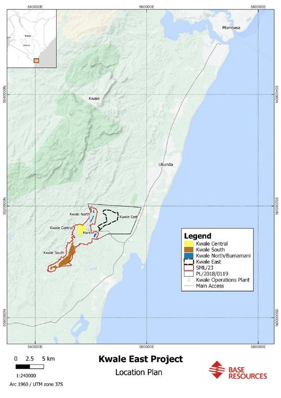
is located within Prospecting Licence 2018/0119
and is the eastern expression of a large, mineralised
Plio-Pleistocene dune system also covering the Kwale Central, South
and North Dunes and the Bumamani deposit – refer to Figure
1.
Kwale East
was considered a near-term mine life extension opportunity due to
its close proximity to Kwale Operations’ infrastructure.
An initial
phase 1 scout auger drilling program (Phase
1)
completed over 2022 and 2023 identified three targets – Magaoni,
Masindini and Zigira – for follow-up aircore drilling as part of
Phase 2.
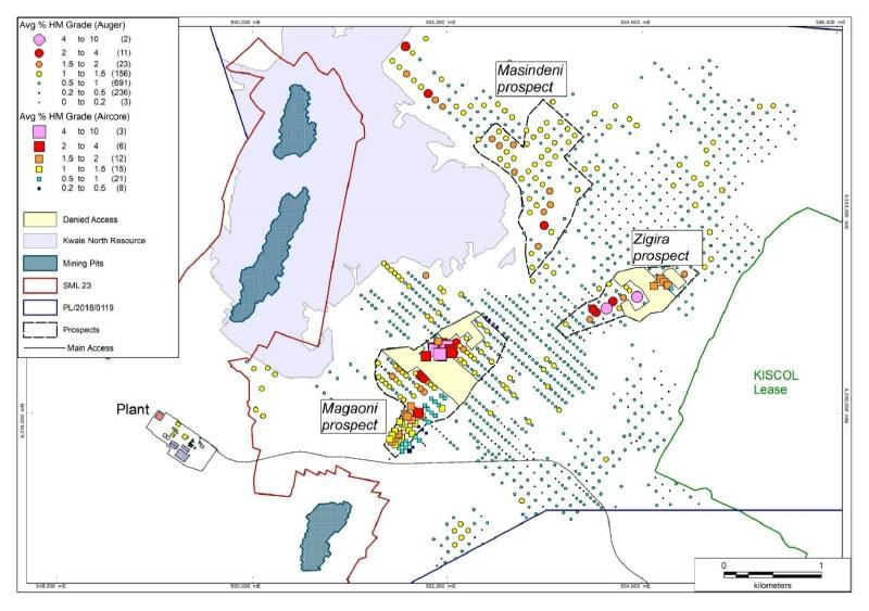
Refer to
Figure 2 for the location of these target areas and the Phase 1
drill holes, and the Company’s announcement of 3 July 2023, titled “Kwale East exploration
drilling update” (the July
Announcement), for
further details in relation to Phase 1.
As was
noted in the July Announcement, land access was a particular
challenge in the more prospective areas of Magaoni and Zigira
during Phase 1, with access to approximately 35% of those target
areas unable to be obtained.
With
community engagement trending positively and optimism over the
Company’s ability to secure the necessary landholder consents, the
Phase 2 program was commenced.
The
priorities for Phase 2 were to:
-
drill the
remaining ~35% of Magaoni and Zigira;
-
complete
infill drilling to achieve 100m north
by 50m east spacing for all three
targets for resource estimate purposes; and
-
twin Phase
1 drill holes with average HM grades of greater than 1% to enable
better sample quality and allow drilling through to basement, as
well as confirm mineralisation.
Despite
securing some additional landholder consents, the Company was
ultimately unable to secure full access to the more prospective
areas in Magaoni and Zigira, largely limiting the program
undertaken for Phase 2 to twinning some of the Phase 1
holes.
In total
for Phase 2,
65 holes for 1,054.5m were completed
in the Magaoni and Zigira target area, resulting in 703 samples –
refer to Figure 2 for the location of these
holes.
While the
Phase 2 assay results confirmed the existence of the mineralisation
identified from the Phase 1 auger program, the Company has decided
to discontinue exploration activities at Kwale
East.
This
decision followed an evaluation of the likely mineralisation for
the three targets using the results from both
Phase 1
and Phase 2
drill programs and applying optimistic assumptions on the
continuity of mineralisation in the Magaoni and Zigira target areas
that were not able to be drilled.
Even on
these optimistic assumptions, the evaluation concluded that there
is unlikely to be sufficient volume or heavy mineral grade to
support an economically viable mining
development.
For
further details about the evaluation undertaken, refer to the
Company’s announcement titled “Kwale Operations to complete mining
at end of 2024”, also released today.
For
further details about the results from Phase 2 drilling, refer to
the Appendices below, comprising a table of assay results for all
drill holes having an average grade equal to or greater than 1% HM
(refer to Appendix 1) and the information provided for the purposes
of Sections 1 and 2 of Table 1 of the JORC Code (refer to Appendix
2).
For
completeness, Appendix 1 also discloses further assay results from
Phase 1 received subsequent to the cut-off for the July
Announcement and having an average grade equal to or greater than
1% HM, and Appendix 2 also contains information provided for the
purposes of Sections 1 and 2 of Table 1 of the JORC Code in respect
for those assay results.
A glossary
of key terms used in this announcement is contained
below.
Competent
Person’s Statement
The
information in this announcement that relates to Kwale East
exploration results is based on, and fairly represents, information
and supporting documentation prepared by Mr. Edwin Owino.
Mr. Owino
is a member of the Australian Institute of
Geoscientists.
Mr. Owino
is employed by Base Resources’ wholly-owned subsidiary, Base
Titanium.
Mr. Owino
holds equity securities in Base Resources and is entitled to
participate in Base Resources’ long-term incentive plan and receive
equity securities under that plan.
Details
about that plan are included in Base Resources’ 2023 Annual Report.
Mr. Owino has sufficient experience that is relevant to the style
of mineralisation and type of deposit under consideration and to
the activity which he is undertaking to qualify as a Competent
Person as defined in the JORC Code and as a Qualified Person for
the purposes of the AIM Rules for Companies.
Mr. Owino
has reviewed this announcement and consents to the inclusion in
this announcement of the Kwale East exploration results and the
supporting information in the form and context in which the
relevant information appears.
Figure
1: Kwale East
Project location
Figure
2: Kwale East
Project drilling location
Appendix
1
Kwale
East drill hole table
All drill
holes have dip of -90 degrees and azimuth of 0 degrees (i.e
vertical).
Local
coordinates given to allow cross reference to cross sections, which
are named after Local_Y.
The table
is sorted by a rounded Local_Y and then by
Local_X.
The
reported intervals are combined ore zones averaged from the surface
with a minimum 3m thickness that
equals or exceed 1% HM.
The reason
for averaging from the surface is that the hydraulic mining method,
which would likely be employed if any of this material were to be
mined, results in the blending of the various ore zones.
|
Hole_ID
|
Type
|
Arc60_X
|
Arc60_Y
|
Local_X
|
Local_Y
|
DTM_Z
|
From
|
To
|
Interval
|
Avg
HM
|
Avg
Slime
|
Avg
OS
|
|
MH348
|
Auger
|
550,036
|
9,516,037
|
2,951
|
10,650
|
70
|
0
|
3
|
3
|
1.4
|
37.9
|
0.9
|
|
MH347
|
Auger
|
550,096
|
9,516,252
|
2,850
|
10,850
|
78
|
0
|
9
|
9
|
1.2
|
28.5
|
0.7
|
|
MH349
|
Auger
|
550,017
|
9,516,461
|
2,650
|
10,950
|
80
|
0
|
7.5
|
7.5
|
1.1
|
33.6
|
0.8
|
|
MH350
|
Auger
|
549,942
|
9,516,529
|
2,550
|
10,950
|
81
|
0
|
7.5
|
7.5
|
1.0
|
30.0
|
1.0
|
|
CD052
|
RCAC
|
551,503
|
9,515,640
|
4,300
|
11,349
|
52
|
0
|
7.5
|
7.5
|
1.0
|
18.7
|
1.1
|
|
CD053
|
RCAC
|
551,464
|
9,515,673
|
4,249
|
11,347
|
56
|
0
|
6
|
6
|
1.6
|
23.9
|
1.9
|
|
CD054
|
RCAC
|
551,430
|
9,515,708
|
4,201
|
11,350
|
56
|
0
|
4.5
|
4.5
|
1.7
|
38.4
|
1.9
|
|
CD059
|
RCAC
|
551,409
|
9,515,731
|
4,170
|
11,353
|
52
|
0
|
4.5
|
4.5
|
1.6
|
30.7
|
1.8
|
|
CD046
|
RCAC
|
551,502
|
9,515,710
|
4,252
|
11,400
|
57
|
0
|
7.5
|
7.5
|
1.3
|
24.6
|
1.9
|
|
CD055
|
RCAC
|
551,463
|
9,515,745
|
4,200
|
11,399
|
57
|
0
|
6
|
6
|
2.1
|
31.4
|
2.6
|
|
CD058
|
RCAC
|
551,435
|
9,515,774
|
4,160
|
11,402
|
52
|
0
|
3
|
3
|
1.6
|
18.6
|
1.7
|
|
CD044
|
RCAC
|
551,571
|
9,515,714
|
4,301
|
11,449
|
53
|
0
|
9
|
9
|
1.0
|
19.1
|
1.0
|
|
CD045
|
RCAC
|
551,534
|
9,515,749
|
4,250
|
11,450
|
58
|
0
|
6
|
6
|
1.7
|
21.4
|
1.2
|
|
CD056
|
RCAC
|
551,498
|
9,515,782
|
4,201
|
11,450
|
59
|
0
|
7.5
|
7.5
|
2.4
|
28.0
|
2.7
|
|
CD057
|
RCAC
|
551,460
|
9,515,816
|
4,150
|
11,450
|
53
|
0
|
4.5
|
4.5
|
1.8
|
29.4
|
2.1
|
|
CD039
|
RCAC
|
551,639
|
9,515,788
|
4,301
|
11,550
|
54
|
0
|
10.5
|
10.5
|
1.5
|
22.3
|
1.3
|
|
CD038
|
RCAC
|
551,607
|
9,515,822
|
4,254
|
11,553
|
58
|
0
|
7.5
|
7.5
|
1.8
|
19.0
|
0.9
|
|
CD037
|
RCAC
|
551,564
|
9,515,856
|
4,200
|
11,549
|
62
|
0
|
9
|
9
|
1.7
|
24.9
|
0.8
|
|
CD060
|
RCAC
|
551,536
|
9,515,893
|
4,154
|
11,558
|
58
|
0
|
4.5
|
4.5
|
1.6
|
28.5
|
1.8
|
|
CD061
|
RCAC
|
551,512
|
9,515,911
|
4,124
|
11,555
|
53
|
0
|
4.5
|
4.5
|
1.4
|
29.6
|
1.2
|
|
CD035
|
RCAC
|
551,670
|
9,515,895
|
4,251
|
11,650
|
60
|
0
|
10.5
|
10.5
|
1.5
|
25.6
|
1.8
|
|
CD036
|
RCAC
|
551,633
|
9,515,930
|
4,200
|
11,651
|
63
|
0
|
12
|
12
|
2.4
|
22.4
|
1.1
|
|
CD064
|
RCAC
|
551,595
|
9,515,964
|
4,149
|
11,650
|
59
|
0
|
4.5
|
4.5
|
2.2
|
26.0
|
1.1
|
|
CD063
|
RCAC
|
551,577
|
9,515,980
|
4,125
|
11,650
|
54
|
0
|
3
|
3
|
2.2
|
25.2
|
1.2
|
|
CD062
|
RCAC
|
551,559
|
9,515,997
|
4,101
|
11,650
|
51
|
0
|
6
|
6
|
1.4
|
25.9
|
1.3
|
|
MH351
|
Auger
|
551,079
|
9,516,436
|
3,450
|
11,650
|
72
|
0
|
12
|
12
|
1.0
|
18.9
|
0.9
|
|
MH346
|
Auger
|
551,005
|
9,516,504
|
3,350
|
11,650
|
69
|
0
|
3
|
3
|
1.0
|
29.8
|
0.8
|
|
CD002
|
RCAC
|
551,769
|
9,515,944
|
4,295
|
11,750
|
56
|
0
|
4.5
|
4.5
|
1.2
|
19.8
|
1.2
|
|
CD003
|
RCAC
|
551,734
|
9,515,974
|
4,251
|
11,750
|
61
|
0
|
10.5
|
10.5
|
1.7
|
25.6
|
1.4
|
|
CD007
|
RCAC
|
551,697
|
9,516,007
|
4,199
|
11,748
|
64
|
0
|
12
|
12
|
2.2
|
22.2
|
1.7
|
|
CD065
|
RCAC
|
551,626
|
9,516,071
|
4,100
|
11,750
|
51
|
0
|
6
|
6
|
1.8
|
24.5
|
3.2
|
|
CD008
|
RCAC
|
551,765
|
9,516,081
|
4,201
|
11,850
|
62
|
0
|
12
|
12
|
1.1
|
24.4
|
1.0
|
|
CD026
|
RCAC
|
551,945
|
9,516,049
|
4,350
|
11,949
|
51
|
0
|
7.5
|
7.5
|
1.5
|
17.7
|
1.5
|
|
CD027
|
RCAC
|
551,909
|
9,516,083
|
4,301
|
11,950
|
54
|
0
|
7.5
|
7.5
|
1.5
|
23.4
|
1.8
|
|
CD028
|
RCAC
|
551,873
|
9,516,117
|
4,251
|
11,951
|
55
|
0
|
6
|
6
|
1.2
|
26.7
|
1.2
|
|
CD029
|
RCAC
|
551,835
|
9,516,151
|
4,200
|
11,950
|
51
|
0
|
3
|
3
|
1.3
|
23.7
|
2.1
|
|
CD031
|
RCAC
|
551,976
|
9,516,157
|
4,300
|
12,050
|
46
|
0
|
4.5
|
4.5
|
1.0
|
15.7
|
2.1
|
|
CD030
|
RCAC
|
551,941
|
9,516,181
|
4,258
|
12,044
|
46
|
0
|
6
|
6
|
1.0
|
14.9
|
3.7
|
|
CD019
|
RCAC
|
551,775
|
9,516,597
|
3,864
|
12,236
|
74
|
0
|
16.5
|
16.5
|
3.8
|
16.8
|
0.5
|
|
CD017
|
RCAC
|
551,941
|
9,516,595
|
3,984
|
12,347
|
72
|
0
|
16.5
|
16.5
|
4.1
|
16.4
|
0.7
|
|
CD018
|
RCAC
|
551,927
|
9,516,612
|
3,960
|
12,347
|
72
|
0
|
18
|
18
|
4.5
|
16.5
|
1.0
|
|
CD004
|
RCAC
|
551,871
|
9,516,656
|
3,891
|
12,345
|
74
|
0
|
18
|
18
|
5.1
|
16.8
|
0.8
|
|
CD015
|
RCAC
|
552,047
|
9,516,634
|
4,040
|
12,445
|
69
|
0
|
16.5
|
16.5
|
3.8
|
18.2
|
1.1
|
|
CD014
|
RCAC
|
552,023
|
9,516,662
|
4,000
|
12,449
|
71
|
0
|
18
|
18
|
4.0
|
15.8
|
0.8
|
|
CD006
|
RCAC
|
551,988
|
9,516,695
|
3,951
|
12,449
|
73
|
0
|
19.5
|
19.5
|
6.5
|
15.6
|
1.6
|
|
CD005
|
RCAC
|
551,943
|
9,516,721
|
3,901
|
12,450
|
74
|
0
|
18
|
18
|
3.9
|
19.0
|
1.3
|
|
CD016
|
RCAC
|
551,902
|
9,516,744
|
3,855
|
12,433
|
74
|
0
|
16.5
|
16.5
|
1.8
|
17.8
|
0.6
|
|
KE923
|
Auger
|
552,010
|
9,516,940
|
3,796
|
12,650
|
72
|
0
|
7.5
|
7.5
|
1.0
|
23.7
|
0.8
|
|
KE922
|
Auger
|
551,976
|
9,516,971
|
3,750
|
12,650
|
71
|
0
|
4.5
|
4.5
|
1.0
|
24.7
|
0.7
|
|
KE920
|
Auger
|
552,007
|
9,517,078
|
3,701
|
12,750
|
66
|
0
|
4.5
|
4.5
|
1.0
|
31.6
|
1.0
|
|
KE901
|
Auger
|
553,202
|
9,517,200
|
4,499
|
13,647
|
58
|
0
|
9
|
9
|
1.2
|
28.3
|
2.2
|
|
KE899
|
Auger
|
553,494
|
9,517,072
|
4,801
|
13,750
|
47
|
0
|
7.5
|
7.5
|
3.5
|
11.6
|
4.8
|
|
KE915
|
Auger
|
553,633
|
9,517,081
|
4,898
|
13,851
|
45
|
0
|
9
|
9
|
5.1
|
12.8
|
3.5
|
|
KE900
|
Auger
|
553,551
|
9,517,145
|
4,794
|
13,843
|
49
|
0
|
4.5
|
4.5
|
1.0
|
10.2
|
2.4
|
|
KE918
|
Auger
|
553,766
|
9,517,083
|
4,994
|
13,941
|
45
|
0
|
6
|
6
|
1.4
|
17.1
|
8.0
|
|
KE912
|
Auger
|
553,503
|
9,517,603
|
4,449
|
14,148
|
59
|
0
|
6
|
6
|
1.1
|
21.8
|
1.1
|
|
KE911
|
Auger
|
553,646
|
9,517,592
|
4,562
|
14,236
|
57
|
0
|
7.5
|
7.5
|
1.2
|
28.9
|
1.4
|
|
NE079
|
Auger
|
552,614
|
9,518,556
|
3,150
|
14,250
|
69
|
0
|
6
|
6
|
1.3
|
37.2
|
0.5
|
|
NE080
|
Auger
|
552,541
|
9,518,624
|
3,050
|
14,250
|
72
|
0
|
9
|
9
|
1.3
|
36.1
|
0.6
|
|
NE104
|
Auger
|
551,657
|
9,519,434
|
1,851
|
14,250
|
90
|
0
|
3
|
3
|
1.3
|
39.5
|
1.0
|
|
NE103
|
Auger
|
551,583
|
9,519,501
|
1,751
|
14,250
|
91
|
0
|
3
|
3
|
1.7
|
37.0
|
1.8
|
|
NE112
|
Auger
|
551,509
|
9,519,569
|
1,650
|
14,250
|
92
|
0
|
3
|
3
|
1.9
|
43.7
|
0.9
|
|
NE119
|
Auger
|
551,436
|
9,519,637
|
1,551
|
14,251
|
90
|
0
|
9
|
9
|
1.4
|
29.9
|
0.4
|
|
CD024
|
RCAC
|
554,120
|
9,517,312
|
5,100
|
14,350
|
47
|
0
|
9
|
9
|
2.1
|
11.8
|
5.1
|
|
NE115
|
Auger
|
553,051
|
9,518,292
|
3,650
|
14,350
|
79
|
0
|
13.5
|
13.5
|
1.8
|
26.2
|
1.1
|
|
NE114
|
Auger
|
552,977
|
9,518,359
|
3,550
|
14,349
|
79
|
0
|
9
|
9
|
1.2
|
28.4
|
0.9
|
|
NE109
|
Auger
|
552,904
|
9,518,426
|
3,451
|
14,350
|
78
|
0
|
9
|
9
|
1.2
|
34.4
|
1.3
|
|
NE120
|
Auger
|
552,534
|
9,518,761
|
2,952
|
14,347
|
80
|
0
|
19.5
|
19.5
|
1.7
|
21.9
|
0.6
|
|
NE121
|
Auger
|
552,460
|
9,518,829
|
2,852
|
14,347
|
82
|
0
|
18
|
18
|
1.6
|
23.7
|
0.9
|
|
NE129
|
Auger
|
552,386
|
9,518,896
|
2,752
|
14,346
|
81
|
0
|
7.5
|
7.5
|
1.0
|
28.6
|
0.6
|
|
NE125
|
Auger
|
552,312
|
9,518,964
|
2,651
|
14,346
|
76
|
0
|
3
|
3
|
1.1
|
41.3
|
0.7
|
|
NE136
|
Auger
|
552,165
|
9,519,099
|
2,452
|
14,346
|
67
|
0
|
4.5
|
4.5
|
1.1
|
34.1
|
1.3
|
|
NE135
|
Auger
|
552,091
|
9,519,167
|
2,351
|
14,347
|
72
|
0
|
4.5
|
4.5
|
1.3
|
41.1
|
1.1
|
|
CD023
|
RCAC
|
554,299
|
9,517,285
|
5,251
|
14,451
|
45
|
0
|
3
|
3
|
1.3
|
5.4
|
2.8
|
|
CD022
|
RCAC
|
554,261
|
9,517,318
|
5,200
|
14,449
|
45
|
0
|
6
|
6
|
2.5
|
7.2
|
11.1
|
|
CD021
|
RCAC
|
554,224
|
9,517,355
|
5,148
|
14,452
|
47
|
0
|
9
|
9
|
1.9
|
11.3
|
6.7
|
|
CD020
|
RCAC
|
554,188
|
9,517,385
|
5,101
|
14,450
|
48
|
0
|
9
|
9
|
1.7
|
8.6
|
3.5
|
|
NE095
|
Auger
|
552,677
|
9,518,770
|
3,051
|
14,450
|
81
|
0
|
18
|
18
|
1.6
|
21.7
|
0.5
|
|
NE122
|
Auger
|
552,528
|
9,518,907
|
2,849
|
14,450
|
83
|
0
|
13.5
|
13.5
|
1.3
|
30.2
|
0.6
|
|
NE148
|
Auger
|
552,238
|
9,519,170
|
2,458
|
14,448
|
69
|
0
|
6
|
6
|
1.1
|
26.8
|
0.8
|
|
NE084
|
Auger
|
551,643
|
9,519,716
|
1,650
|
14,449
|
103
|
0
|
7.5
|
7.5
|
1.2
|
37.2
|
0.1
|
|
NE085
|
Auger
|
551,571
|
9,519,784
|
1,550
|
14,450
|
107
|
0
|
6
|
6
|
1.8
|
44.9
|
0.0
|
|
NE124
|
Auger
|
552,448
|
9,519,111
|
2,652
|
14,547
|
81
|
0
|
3
|
3
|
1.0
|
27.9
|
0.3
|
|
NE123
|
Auger
|
552,374
|
9,519,179
|
2,552
|
14,547
|
78
|
0
|
3
|
3
|
1.1
|
34.4
|
0.3
|
|
NE110
|
Auger
|
551,779
|
9,519,864
|
1,650
|
14,650
|
102
|
0
|
9
|
9
|
1.1
|
27.4
|
0.3
|
|
NE099
|
Auger
|
553,407
|
9,518,519
|
3,759
|
14,758
|
73
|
0
|
7.5
|
7.5
|
1.1
|
32.8
|
2.1
|
|
NE118
|
Auger
|
552,953
|
9,518,924
|
3,151
|
14,750
|
81
|
0
|
15
|
15
|
1.4
|
26.8
|
0.5
|
|
NE139
|
Auger
|
553,308
|
9,518,866
|
3,452
|
14,947
|
77
|
0
|
16.5
|
16.5
|
1.2
|
25.3
|
1.4
|
|
NE133
|
Auger
|
553,234
|
9,518,933
|
3,352
|
14,946
|
76
|
0
|
13.5
|
13.5
|
1.2
|
27.4
|
1.8
|
|
NE144
|
Auger
|
553,081
|
9,519,213
|
3,050
|
15,049
|
81
|
0
|
9
|
9
|
1.2
|
30.7
|
0.5
|
|
NE089
|
Auger
|
553,143
|
9,519,428
|
2,950
|
15,250
|
83
|
0
|
9
|
9
|
1.1
|
36.0
|
0.8
|
|
NE107
|
Auger
|
553,942
|
9,518,968
|
3,850
|
15,450
|
70
|
0
|
3
|
3
|
1.0
|
36.2
|
0.6
|
|
NE105
|
Auger
|
553,868
|
9,519,035
|
3,751
|
15,450
|
75
|
0
|
6
|
6
|
1.1
|
37.5
|
2.6
|
|
NE090
|
Auger
|
553,720
|
9,519,170
|
3,550
|
15,450
|
80
|
0
|
12
|
12
|
1.1
|
32.2
|
1.0
|
|
NE096
|
Auger
|
554,200
|
9,519,545
|
3,651
|
16,050
|
57
|
0
|
3
|
3
|
1.1
|
26.7
|
2.4
|
Appendix
2
JORC
Code - Section 1 Sampling Techniques and Data
|
Criteria
|
Explanation
|
Comment
|
|
Sampling
techniques
|
Nature
and quality of sampling (e.g., cut channels, random chips, or
specific specialised industry standard measurement tools
appropriate to the minerals under investigation, such as down hole
gamma sondes, or handheld XRF instruments, etc). These examples
should not be taken as limiting the broad meaning of
sampling.
Include
reference to measures taken to ensure sample representivity and the
appropriate calibration of any measurement tools or systems
used.
Aspects
of the determination of mineralisation that are Material to the
Public Report. In cases where ‘industry standard’ work has been
done this would be relatively simple (e.g., ‘reverse circulation
drilling was used to obtain 1 m samples from which 3 kg was
pulverised to produce a 30 g charge for fire assay’). In other
cases, more explanation may be required, such as where there is
coarse gold that has inherent sampling problems. Unusual
commodities or mineralisation types (e.g., submarine nodules) may
warrant disclosure of detailed information.
|
For holes
prefixed GN, KE, MH and NE mechanised auger drilling was used to
obtain 1.5m samples from which approximately 4.0kg was collected
via composite grab sampling of a homogenised sample to produce a
sub-sample for HM analysis utilising heavy liquid separation,
magnetic separation and XRF assay.
All holes
were sampled over consistent 1.5m intervals.
Several
programs of twin drilling of air core holes have been undertaken
and, while some variability was observed, it was concluded that
auger drilling is appropriate for reconnaissance drilling to
identify mineralisation potential.
For holes
prefixed CD, reverse circulation aircore drilling was used to
collect the entire 1.5m downhole sample averaging ~10kg from which
approximately 3kg was collected via two-stage riffle
splitting.
Samples
were analysed by mineral sands industry standard techniques of
screening, desliming and heavy liquid separation using SPT (sodium
polytungstate: SG = 2.85g/cm3).
XRF
analysis of HM magnetic fractions was used to define the VHM
content.
|
|
Drilling
techniques
|
Drill
type (e.g., core, reverse circulation, open-hole hammer, rotary air
blast, auger, Bangka, sonic, etc) and details (e.g., core diameter,
triple or standard tube, depth of diamond tails, face-sampling bit
or other type, whether core is oriented and if so, by what method,
etc).
|
Holes
prefixed GN, KE, MH and NE were drilled using trailer mounted
mechanised auger equipment, with the fleet comprising three rigs
utilising the dead stick auger method (0.5m sample runs) and one
rig utilising the continuous flight auger method.
All holes
were drilled vertically with the trailer levelled using site
preparation and manual jack legs.
Hole
diameter was approximately 4” or 102 mm.
Holes
prefixed CD were drilled used a truck mounted RCAC EVH 2100 drill
rig using remet drill rods of 75mm diameter and a 3 blade aircore
vacuum sampling bit.
All holes
were drilled vertically with the rig levelled using site
preparation and rear hydraulic jacks.
|
|
Drill
sample recovery
|
Method
of recording and assessing core and chip sample recoveries and
results assessed.
Measures
taken to maximise sample recovery and ensure representative nature
of the samples.
Whether
a relationship exists between sample recovery and grade and whether
sample bias may have occurred due to preferential loss/gain of
fine/coarse material.
|
Sample
condition was logged at the rig as either good, moderate or poor,
with good meaning not contaminated and appropriate sample size
(recovery), moderate meaning not contaminated, but sample over or
undersized, and poor meaning contaminated or grossly
over/undersized.
It is
recognised that open hole auger drilling is subject to potential
sample contamination by smearing as the sample is retrieved (both
methods) and material falling downhole during running of the drill
string (dead stick method).
To counter
downhole contamination the driller nominates material for rejection
as potential contamination on each 0.5m drill run.
Moist
ground conditions meant that best sample quality for aircore
drilling was found to be achieved via slow penetration with water
injection to aid in the sample recovery.
No
relationship is believed to exist between grade and sample
recovery.
No bias is
also believed to occur due to loss of fine material.
|
|
Logging
|
Whether
core and chip samples have been geologically and geotechnically
logged to a level of detail to support appropriate Mineral Resource
estimation, mining studies and metallurgical
studies.
Whether
logging is qualitative or quantitative in nature. Core (or costean,
channel, etc) photography.
The
total length and percentage of the relevant intersections
logged.
|
All
samples were visually checked on site and a summary log was
completed by the site geologist. For the initial auger drilling,
detailed logging was completed off-site to avoid speculation by
community observers, whereas for the aircore drilling, logging was
completed on-site to also capture ground
conditions.
Samples
are logged for lithotype, grain size, colour, hardness, and
moisture content.
Logging
was based on a representative grab sample that was panned for heavy
mineral estimation and host material observations.
Logging
codes were developed into the logging software (LogChief) to
capture observations on lithology, colour, grainsize, induration
and estimated mineralisation.
Any
relevant comments e.g., water table, hardness, gangue HM components
and stratigraphic markers (e.g fossilised wood) were included to
aid in the subsequent geological modelling.
|
|
Sub-sampling
techniques and sample preparation
|
If
core, whether cut or sawn and whether quarter, half or all core
taken.
If
non-core, whether riffled, tube sampled, rotary split, etc and
whether sampled wet or dry.
For
all sample types, the nature, quality and appropriateness of the
sample preparation technique.
Quality
control procedures adopted for all sub-sampling stages to maximise
representivity of samples.
Measures
taken to ensure that the sampling is representative of the in-situ
material collected, including for instance results for field
duplicate/second-half sampling.
Whether
sample sizes are appropriate to the grain size of the material
being sampled.
|
For the
auger holes an approximate 25% split of the drilled sample interval
is collected on site via manual cone and quarter composite grab
sampling.
For
aircore holes the entire sample interval was collected mostly wet
and bagged on site in polyweave bags with internal plastic lining
to avoid loss of slimes. Following air drying of excess moisture an
approximate 25% split of the drilled sample interval was collected
via riffle splitting.
The split
sample was processed in a dedicated sample preparation facility
where it was air-dried when weather permitted, otherwise it was
oven dried during the rainy season.
After
drying, the sample was rotary split to produce a ~200-400g sample
for analytical work.
The
remaining drill sample material was combined and split down to
~2-3kgs for storage.
Improvements
to the sample preparation stage were made in recent years to ensure
industry best practice and to deliver a high degree of confidence
in the results.
These
included the following:
-
A formalised process flow was generated, posted in all sample
preparation areas and used to train and monitor sample preparation
staff.
-
Regular monitoring was completed by Base Titanium senior
staff.
-
Field samples were left in their bags for initial air-drying to
avoid sample loss.
-
TSPP dispersant was introduced to decrease attrition time and
improve slimes recovery.
A range of attrition times (with 5% TSPP) were trialled and plotted
against slimes recovery figures to determine optimum attrition time
(15 minutes).
-
Staff were trained to use paint brushes and water spray rather than
manipulate sample through slimes screen by hand to remove the
potential for screen damage.
-
A calibration schedule was introduced for scales used in the sample
preparation stage.
-
The introduction of LIMS software allowed the capture of sample
preparation data digitally at inception and synchronisation in
real-time to the master Kwale Laboratory database.
-
Slimes screen number recorded to isolate batches should re-assay be
required due to poor adherence to procedure or to identify screen
damage.
The sample
preparation flow sheet follows conventional mineral sands processes
but departed from standard mineral sand practices in one respect;
the samples were generally not oven dried prior to de-sliming to
prevent clay minerals being baked onto the HM grains (because the
HM fractions were to be used in further mineralogical test
work).
Instead, a
separate sample was split and dried to determine moisture content,
which was accounted for mathematically.
Pre-soaking
of the sample TSPP dispersant solution ensured a more efficient
de-sliming process and avoided potentially under-reporting slimes
content.
QA/QC
procedures involved the following:
-
Prepared laboratory duplicate split samples were processed at every
20th
sample.
-
Prepared laboratory repeat samples were processed at every 7th
sample.
The manual
hard-copy sample preparation records are maintained in files in the
event of cross-references due to identified scribing errors into
LIMS software.
The sample
size is considered appropriate for the grain size of the material
because the grade of HM is measured in per cent.
|
|
Quality
of assay data and laboratory tests
|
The
nature, quality and appropriateness of the assaying and laboratory
procedures used and whether the technique is considered partial or
total.
For
geophysical tools, spectrometers, handheld XRF instruments, etc,
the parameters used in determining the analysis including
instrument make and model, reading times, calibrations factors
applied and their derivation, etc.
Nature
of quality control procedures adopted (e.g., standards, blanks,
duplicates, external laboratory checks) and whether acceptable
levels of accuracy (i.e., lack of bias) and precision have been
established.
|
Samples
were analysed by conventional mineral sands techniques of
screening, desliming and heavy liquid separation using SPT (sodium
polytungstate: SG = 2.85g/cm3).
XRF
analysis of HM magnetic fractions was used to estimate the VHM
content.
All drill
samples were submitted to the Kwale Operations laboratory, with the
following approach adopted.
-
All samples were dried and weighed.
-
Split to a ~200-400 g sub-sample using a rotary
splitter.
-
Wet screened using 45 µm and 1 mm sieves, to generate oversize and
sand fractions, with slimes lost during screening and calculated by
difference.
-
Sand fraction processed by SPT heavy liquid separation to generate
a HM fraction.
-
HM fraction subject to magnetic separation on a roll magnet to
generate a magnetic (Mag) fraction and non-magnetic (NonMag)
fraction.
-
XRF analysis of magnetic fractions, with rutile (assumed 95% TiO2)
calculated from TiO2 assay of NonMag by dividing by 0.95, zircon
calculated from ZrO2 assay of NonMag, and ilmenite (assumed 54%
TiO2 average) calculated from TiO2 assay of Mag by dividing by
0.54.
-
Various quality control samples were submitted routinely to ensure
assay quality.
A total of 494 duplicate field samples, 492
laboratory duplicate samples, 906 laboratory repeat samples and 26
internal field standards have been assayed at Kwale Operations’
site laboratory.
|
|
Verification
of sampling and assaying
|
The
verification of significant intersections by either independent or
alternative company personnel.
The
use of twinned holes.
Documentation
of primary data, data entry procedures, data verification, data
storage (physical and electronic) protocols.
Discuss
any adjustment to assay data.
|
Drill hole
logging and site sample data was collected electronically in
Maxwell LogChief software, installed on field Panasonic Toughpads
and which synchronise directly to the Maxwell DataShed exploration
database software hosted on the Base Titanium network
server.
Assay data
was captured electronically via LIMS software and merged with
logging and sample data in Datashed.
No
adjustment to assay data was made.
|
|
Location
of data points
|
Accuracy
and quality of surveys used to locate drill holes (collar and
down-hole surveys), trenches, mine workings and other locations
used in Mineral Resource estimation.
Specification
of the grid system used.
Quality
and adequacy of topographic control.
|
Proposed
drill holes were sited on the ground using hand-held Garmin GPS
units which have an accuracy of between 3 and 5m. The auger drill
collars were surveyed using the same instrumentation while 60 out
of 65 aircore holes were surveyed using real time kinematic (RTK)
DGPS unit.
The survey
Geodetic datum utilised was UTM Arc 1960, used in East Africa Arc
1960 references the Clark 1880 (RGS) ellipsoid and the Greenwich
prime meridian.
All survey
data used has undergone a transformation to the local mine grid
from the standard UTM Zone 37S (Arc 1960). The local Grid is
rotated 42.5o,
which aligns the average strike of the deposit with local North and
is useful for both grade interpolation and mining reference during
production.
The drill
collars were projected to a merged local LIDAR and SRTM digital
terrain model
|
|
Data
spacing and distribution
|
Data
spacing for reporting of Exploration Results.
Whether
the data spacing, and distribution is sufficient to establish the
degree of geological and grade continuity appropriate for the
Mineral Resource and Ore Reserve estimation procedure(s) and
classifications applied.
Whether
sample compositing has been applied.
|
The drill
data spacing for the drilling was nominally 100m X, 50m Y and 1.5m
Z.
Variations
from this spacing resulted from access challenges.
This
spacing and distribution is considered sufficient to establish the
degree of geological and mineralisation continuity appropriate for
reconnaissance exploration.
No sample
compositing has been applied for HM, slimes, oversize and XRF
assays.
|
|
Orientation
of data in relation to geological structure
|
Whether
the orientation of sampling achieves unbiased sampling of possible
structures and the extent to which this is known, considering the
deposit type.
If the
relationship between the drilling orientation and the orientation
of key mineralised structures is considered to have introduced a
sampling bias, this should be assessed and reported if
material.
|
With the
geological setting being a layered dunal/fluvial/maritime
sequences, the orientation of the deposit mineralisation in general
is sub-horizontal.
All drill
holes were orientated vertically to penetrate the sub-horizontal
mineralisation orthogonally.
Hole
centres were spaced nominally at 50-200m.
This
cross-profiles the dune so that variation can be
determined.
Down hole
intervals were nominated as 1.5m.
This
provides adequate sampling resolution to capture the distribution
and variability of geology units and mineralisation encountered
vertically down hole.
The
orientation of the drilling is considered appropriate for testing
the horizontal and vertical extent of mineralisation without
bias.
|
|
Sample
security
|
The
measures taken to ensure sample security.
|
Sample
residues from the preparatory stage were transferred to pallets and
stored in a locked shed beside the warehouse at Kwale
Operations.
Residues
from the Kwale Operations site laboratory were placed in labelled
bags and stored in numbered boxes.
Boxes were
placed into a locked container beside the
laboratory.
Sample
tables are housed on a secure, network-hosted SQL
database.
Full
access rights are only granted to the Exploration Manager and
senior IT personnel.
Data is
backed up every 12 hours and stored in perpetuity on a secure, site
backup server.
|
|
Audits
or reviews
|
The
results of any audits or reviews of sampling techniques and
data.
|
In-house
reviews were undertaken by Mr. Scott Carruthers and Mr. Ian
Reudavey, both employees of the Base Resources group and Competent
Persons under the JORC Code.
|
Section
2 Reporting of Exploration Results
(Criteria
listed in the preceding section also apply to this
section.)
|
Criteria
|
Explanation
|
Comment
|
|
Mineral tenement and land tenure status
|
Type,
reference name/number, location and ownership including agreements
or material issues with third parties such as joint ventures,
partnerships, overriding royalties, native title interests,
historical sites, wilderness or national park and environmental
settings.
The
security of the tenure held at the time of reporting along with any
known impediments to obtaining a licence to operate in the
area.
|
The Kwale
East exploration area is situated on a Prospecting Licence 100%
owned by Base Titanium– PL/2018/0119 located in Kwale County,
Kenya.
Base
Titanium is a wholly owned subsidiary of ASX and AIM-listed
resources company, Base Resources.
The
40km2
Prospecting
Licence was re-granted on 26 of May 2021 for a second, three-year
term ending 25 May 2024.
The PL is
in good standing with the Kenya State Department of Mining at the
time of reporting, with all statutory reporting and payments up to
date.
Local
landowners have been generally supportive of exploration
activities, though blanket access was not
achieved.
The
existing Special Mining Lease No. 23 is adjacent to the
PL.
The SML
boundary has been varied on multiple occasions, most recently to
include the Bumamani Project deposits.
The Kenyan
Mining Act 2016 includes a provision for existing mineral rights to
transition to mining licences upon their expiry on a priority
basis.
Landowner
access permission is required to both complete the exploration
program and then progress conversion of the PL to a mining
licence.
The Mining
Act 2016 provides greater flexibility on securing land rights,
specifically allowing for a mineral right to be issued on private
land.
The Mining
Act 2016 additionally, provides for fair and adequate compensation
to be paid to lawful landowners, occupiers and users.
|
|
Exploration done by other parties
|
Acknowledgment
and appraisal of exploration by other parties.
|
No
historical exploration by third parties was undertaken in the Kwale
East area.
|
|
Geology
|
Deposit
type, geological setting and style of
mineralisation.
|
The Kwale
East deposits are primarily hosted in reddish dunal sands (Ore Zone
1) which is underlain by a transitional and occasionally lateritic
zone (Ore Zone 4).
To the
east and around the 50-60mRL, these deposits are hosted in shallow
paleo-beach sands (Ore Zone 20) originating from a Pleistocene
marine transgression event.
This zone
is low in slime and typically has a high valuable heavy mineralogy
content.
All three
formations have a regional strike direction of about 40 degrees
East of North and range in age from mid-Pliocene to
Pleistocene.
|
|
Drill
hole Information
|
A
summary of all information material to the understanding of the
exploration results including a tabulation of the following
information for all Material drill holes:
-
easting
and northing of the drill hole collar
-
elevation or RL (Reduced Level – elevation above sea level in
metres) of the drill hole collar
-
dip and azimuth of the hole
-
down hole length and interception depth
-
hole
length.
If the
exclusion of this information is justified on the basis that the
information is not Material and this exclusion does not detract
from the understanding of the report, the Competent Person should
clearly explain why this is the case.
|
A
tabulation of drilling data with significant intersections ≥1% HM
is included in Appendix 1.
All drill
hole locations are shown in Figure 2, and those holes not tabulated
have not reported significant intersections.
The
exclusion of detailed collar information for all drill holes is
justified on the basis that:
-
auger drilling represents a reconnaissance exploration tool with
over 1,000 holes drilled; and
-
the air core drilling completed was primarily for better quality
samples in areas identified as prospective by the auger drilling
program and to ensure the holes were drilled down to
basement.
Drilling
by year (max, min and average depths) is as follows.
-
123 air
core drill holes (depth: max 33m, min 6m, avg 15m).
-
Total
1,851.5m drilled
-
1,134
auger drill holes (depth: max 24m, min 3m, avg 11.5m).
-
Total
13,105.5m drilled by auger
-
65 aircore
drill holes (depth: max 24m, min 6m, avg 16m).
-
Total
1,054.5m drilled by aircore
All drill
holes are drilled vertically (-90 degrees).
All
collars have been projected to the DTM surface.
|
|
Data aggregation methods
|
In
reporting Exploration Results, weighting averaging techniques,
maximum and/or minimum grade truncations (e.g., cutting of high
grades) and cut-off grades are usually Material and should be
stated.
Where
aggregate intercepts incorporate short lengths of high-grade
results and longer lengths of low-grade results, the procedure used
for such aggregation should be stated and some typical examples of
such aggregations should be shown in detail.
The
assumptions used for any reporting of metal equivalent values
should be clearly stated.
|
Exploration
results are reported as length weighted averages from
surface.
No grade
cutting has been applied and a nominal cut-off grade of 1% HM has
been utilised.
However,
lower grade intervals may be included to provide geological
continuity and in recognition of bulk mining techniques used for
mineral sands.
No metal
equivalent values were used.
|
|
Relationship between mineralisation widths and intercept
lengths
|
These
relationships are particularly important in the reporting of
Exploration Results.
If the
geometry of the mineralisation with respect to the drill hole angle
is known, its nature should be reported.
If it
is not known and only the down hole lengths are reported, there
should be a clear statement to this effect (e.g., ‘down hole
length, true width not known’).
|
The
deposit sequences are sub-horizontal, and the vertically inclined
holes are a fair representation of true thickness.
|
|
Diagrams
|
Appropriate
maps and sections (with scales) and tabulations of intercepts
should be included for any significant discovery being reported.
These should include, but not be limited to a plan view of drill
hole collar locations and appropriate sectional
views.
|
See body
of the announcement - Figure 2.
Additional
diagrams, including cross sections, have not been included as no
significant discovery is being reported.
Given the
Company’s decision to discontinue exploration activities at Kwale
East, these are not considered material.
Further,
detailed cross sections were included in the July
Announcement.
|
|
Balanced reporting
|
Where
comprehensive reporting of all Exploration Results is not
practicable, representative reporting of both low and high grades
and/or widths should be practiced to avoid misleading reporting of
Exploration Results.
|
The
drilling location plan shows the average HM assay results for all
drill holes.
|
|
Other substantive exploration data
|
Other
exploration data, if meaningful and material, should be reported
including (but not limited to): geological observations;
geophysical survey results; geochemical survey results; bulk
samples – size and method of treatment; metallurgical test results;
bulk density, groundwater, geotechnical and rock characteristics;
potential deleterious or contaminating substances.
|
Geological
observations suggest that the Kwale East dunal material contains
significantly lower slimes than the deposits currently being
mined.
This would
be beneficial to support the co-disposal of tails, while still
having sufficient slimes to support hydraulic mining.
Due to the
reconnaissance nature of exploration to date and the decision to
not proceed with further exploration, there is no other substantive
exploration data to report.
|
|
Further work
|
The
nature and scale of planned further work (e.g., tests for lateral
extensions or depth extensions or large-scale step-out
drilling).
Diagrams
clearly highlighting the areas of possible extensions, including
the main geological interpretations and future drilling areas,
provided this information is not commercially
sensitive.
|
Exploration
activities at Kwale East have been discontinued.
This
decision followed an evaluation of the likely mineralisation for
the three targets using the results from the Phase 1 and Phase 2
drill programs and applying optimistic assumptions on the
continuity of mineralisation in the Magaoni and Zigira target areas
that were not able to be drilled.
Even on
these optimistic assumptions, the evaluation indicated that there
is unlikely be sufficient volume or heavy mineral grade to support
an economically viable mining development.
For
further details about the evaluation undertaken, refer to the
Company’s announcement titled “Kwale Operations to transition to
post-mining at end of 2024 as planned”, also released
today.
|
Glossary
|
Base
Titanium
|
Base
Resources’ wholly-owned Kenyan operating subsidiary and the owner
and operator of Kwale Operations.
|
|
collar
|
Location
of a drill hole.
|
|
Competent
Person
|
Has the
meaning given in the JORC Code.
The JORC
Code requires that a Competent Person be a Member or Fellow of The
Australasian Institute of Mining and Metallurgy, or of the
Australian Institute of Geoscientists, or of a ‘Recognised
Professional Organisation’.
A
Competent Person must have a minimum of five years’ experience
working with the style of mineralisation or type of deposit under
consideration and relevant to the activity which that person is
undertaking.
|
|
DTM
|
Digital
Terrain Model.
|
|
GPS
|
Global positioning system.
|
|
HM
|
Heavy
mineral.
|
|
JORC
Code
|
The
Australasian Code for Reporting of Exploration Results, Mineral
Resources and Ore Reserves, as published by the Joint Ore Reserves
Committee of The Australasian Institute of Mining and Metallurgy,
Australian Institute of Geoscientists and Minerals Council of
Australia.
|
|
Kwale
Operations
|
Base
Titanium’s mineral sands mining operations in Kwale County,
Kenya.
|
|
LIDAR
|
Light
Detection and Ranging, a remote sensing method that uses pulsed
laser to measure ranges.
|
|
LIMS
|
Laboratory
information management system.
|
|
PL
|
Prospecting
licence.
|
|
QA/QC
|
Quality
assurance and quality control.
|
|
RCAC
|
Reverse
circulation aircore drilling method
|
|
RL
|
Reduced
level, equating elevations with reference to a common assumed
vertical datum
|
|
SG
|
Specific
gravity, or relative density.
|
|
SML
|
Special
mining lease.
|
|
SPT
|
Sodium
polytungstate heavy liquid used for mineral separation based on
relative density.
|
|
SQL
|
Structured
Query Language, a standardized programming language used to manage
relational databases.
|
|
SRTM
|
Shuttle
Radar Topography Mission, a modified radar system used by a Space
Shuttle Endeavour mission to capture a high-resolution topographic
database of the earth.
|
|
TSPP
|
Sodium
(Tetra) Pyrophosphate.
|
|
UTM
|
Universal
Transverse Mercator, a plane coordinate grid system.
|
|
VHM
|
Valuable
heavy mineral.
|
|
XRF
|
A
spectroscopic method used to determine the chemical composition of
a material through analysis of secondary X-ray emissions, generated
by excitation of a sample with primary X-rays that are
characteristic of a particular element.
|
ENDS.
For
further information contact:
|
Australian
Media Relations
|
UK Media
Relations
|
|
Citadel
Magnus
|
Tavistock
Communications
|
|
Cameron
Gilenko and Michael Weir
|
Jos Simson
and Gareth Tredway
|
|
Tel: +61 8
6160 4900
|
Tel: +44
207 920 3150
|
About
Base Resources
Base
Resources is an Australian based, African focused, mineral sands
producer and developer with a track record of project delivery and
operational performance.
The
Company operates the established Kwale Operations in Kenya and is developing the Toliara Project in
Madagascar.
Base
Resources is an ASX and AIM listed company.
Further
details about Base Resources are available at
www.baseresources.com.au.
PRINCIPAL
& REGISTERED OFFICE
Level 3,
46 Colin Street
West Perth, Western
Australia, 6005
Email:
info@baseresources.com.au
Phone: +61
8 9413 7400
Fax: +61 8
9322 8912
NOMINATED
ADVISER & JOINT BROKER
Canaccord
Genuity Limited
James Asensio / Raj Khatri / George
Grainger
Phone: +44
20 7523 8000
JOINT
BROKER
Berenberg
Matthew Armitt / Detlir Elezi
Phone: +44
20 3207 7800